HARDWARE – SOFTWARE CONSULTANT
![]()
Scientific Applications International Corporation, La Jolla, California -1/94 to 12/94
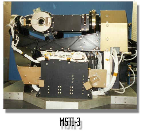
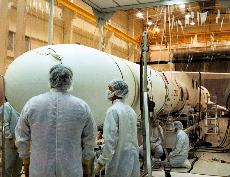
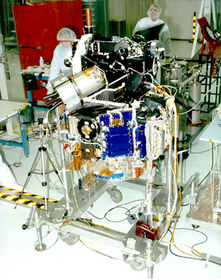
Designed 3 Mil-Spec VME bus interface cards for a multi spectral sensor for a low-orbit spacecraft called MSTI-3. The Miniature Seeker Technology Integration (MSTI-3) satellite is to be used to monitor and track ICBM launches while in low earth orbit.
It was deployed via airplane launch on a Pegasus rocket in May 1996. The short wave and medium wave infrared cameras used Stirling Cycle Coolers for reducing the temperatures of the detectors and filters wheels to 270 degrees below zero.
The program was sponsored by the Ballistic Missile Defense Organization and U.S. Air Force. MSTI-3 set new records for the rapid development of sophisticated, lower-cost spacecraft.
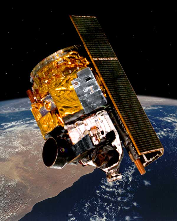
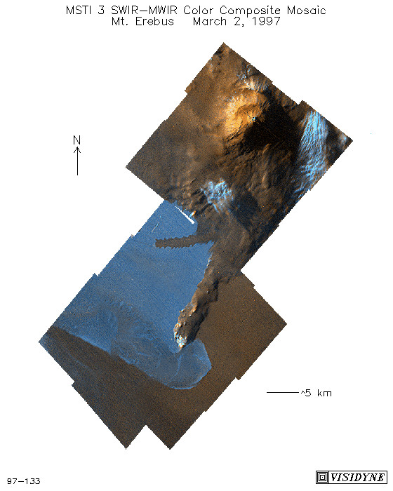
This spacecraft is one of the first hyper-spectral imager instruments ever flown in space. The spacecraft collected over 3 million short-wave and mid-wave infrared images as well as hyper-spectral images.
MSTI-3 exceeded its design lifetime by over 50% before being de-orbited in Dec. 1997.
MSTI-3 is also the reference design for the U.S. Space-Based Infrared System (SBIRS-LOW) architecture for National Ballistic Missile Defense being evaluated. http://www.sbirslow.com/ProjectDescriptionGeo.asp
MSTI-3 also happened to be the target for the first test of a LASER against an orbiting satellite. http://www.fas.org/spp/military/program/nssrm/initiatives/msti.htm
http://www.nytimes.com/1997/10/03/us/us-to-fire-laser-weapon-at-a-satellite.html
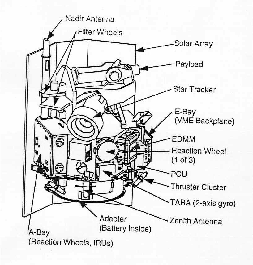
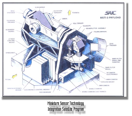
The three VME boards each had a VMEbus interface FPGA I designed and two other FPGAs that provided control and status of the telescope pointing system. I used Workview (View Logic – View Sim – ACTEL Designer) for the FPGA (8000 gates, 132-pins) designs. The three boards were:
VMEbus Dual-Axis Telescope Steering Mirror Servo Controller with 19-bit optical encoders.
VMEbus Dual (Intel 8051) filter wheel (stepper motor) controllers with 16-bit resolvers. The stepper motors had to operate at – 270 degrees F. This was one of the toughest parts of the design.
VMEbus 24-channel data acquisition (payload temperature/ sensor monitoring) interface.
Wrote test software for each card using ‘C’.